Abstract
The VR9500 and VR10500 vibration controllers can verify the calibration of an accelerometer or other input using the VibrationVIEW software. This software feature also includes the option to write to TEDS (transducer electronic data sheet).
Objective
Check the input sensor sensitivity and verify/calibrate the sensor. If applicable, update the TEDS info.
Solution
VR9106 software package (for VR9500/VR10500 systems) or VR‐632 (for VR8500 systems); requires VibrationVIEW Sine software. Contact sales for more information.
How to Verify Accelerometer Calibration
Use a VR I/O unit and the VibrationVIEW software to verify the calibration of your accelerometers. The software provides an easy interface to calculate accelerometer sensitivity. The process involves:
- Performing a sine sweep
- Controlling on a reference accelerometer
- Producing a calibration report suitable for calibration record keeping
VibrationVIEW automatically calculates the accelerometer sensitivity at the selected frequency. The process requires at least 2 input channels (one for a reference accelerometer and one for the accelerometer undergoing calibration), the Sine software (VR9100) and calibration add-on package, a reference accelerometer, and a shaker system.
Directions
The Accelerometer Calibration Verification software measures the sensitivity level of an accelerometer connected to the Channel 2 input using an accelerometer on the Channel 1 input as the calibrated reference accelerometer. After measuring the sensitivity level, the software runs a frequency sweep to measure the accelerometer’s frequency response. In the following directions, we will use the following definitions:
- UUT: Unit Under Test: the accelerometer connected to the Channel 2 input (the accelerometer to be calibrated); you can verify more than one channel at a time
- REF: Reference Accelerometer: the accelerometer connected to the Channel 1 input (measurement standard)
We will use the sample test profile Calibrate Channel 2.vsp to demonstrate the use of this software. It is assumed that your shaker has both the REF and UUT accelerometers connected such that they both measure the same acceleration. This connection is typically achieved using a piggyback mount at the center of the shaker.
Open the Sample Test
In VibrationVIEW, load the sample test by selecting the Open Test toolbar button or Test > Open Test from the menu.

Figure 1. Open Test toolbar button.
Select Calibrate Channel 2.vsp from the list. It may be necessary to change the file type to “Sine Tests (*.vsp).”
To view or change the test settings, select Edit Test or Test > Edit Test Settings.

Figure 2. Edit Test toolbar button.
Define the Frequency Sweep
The frequency range and amplitude profile for the frequency sweep are defined on the Profile tab of the test settings. The example file sweeps from 10Hz to 4,000Hz at a constant amplitude of 1G peak.
Set the frequency sweep values that are appropriate for your accelerometer. The frequency response is reported as a ratio of UUT relative to REF, so the amplitude does not need to be constant over the entire frequency range.
For example, it may be necessary to transition to a constant displacement at low frequencies. To do this, select the Insert button to add another level. Set the first level to displacement values and the second level to acceleration values. Then, select the Calc button to compute the cross‐over frequency (Figure 3).
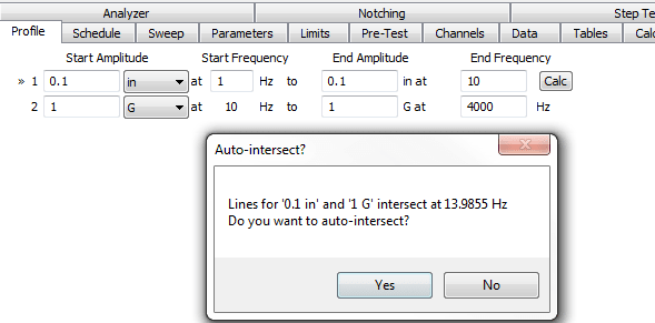
Figure 3. Message that appears after the user selects the Calc button.
Schedule the Test
The next step is to define the sequence of events to run during the test. Select the Schedule tab. The typical accelerometer calibration test involves three steps:
Level 1: Calibrate Ch. 2
Holds the REF accelerometer at a constant frequency and amplitude and measures the sensitivity of the UUT accelerometer at these values. Typically, you will want to run 30 seconds for an accurate measurement. The Modifier value selects the acceleration, velocity, or displacement level for the calibration measurements.
Level 2: Sweep up
Runs a frequency sweep from 20Hz with a duration of 1 sweep. The sweep will start at 20Hz and stop at the maximum frequency defined on the Profile tab. The Modifier level defines the amplitude relative to the values on the Profile tab.
Level 3: Open Report
Creates a report using the selected template file. When the test reaches this step, the program will prompt the operator for a report file name. After the operator enters a file name, the software will generate a report that will open in your word processor.
The Sweep tab defines the tolerance and abort levels for the test and defines the sweep rate for the frequency sweep. Change these values if you want a faster or slower frequency sweep.
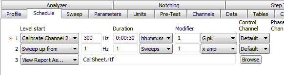
Figure 4. Schedule tab with “Calibrate Channel 2,” “Sweep up from,” and “View Report As…” levels.
Run the Test
To run the test, select the Run button.
Note: You can customize or modify the report template for more automation or additional information. Contact Vibration Research support for assistance or navigate to the How To section of the manual or help file for details on creating customized reports.